Using a Touch Plate with BobsCNC
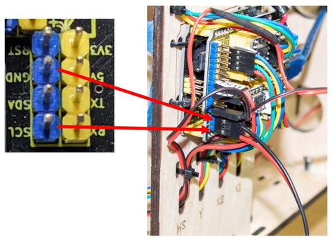
A touch plate is a simple electrical switch. One side of the circuit is wired to the GND pin on the Arduino controller shield, and the other side is wired to the SCL pin. At the other end of the wire, one side is connected to a touch plate and the other to an alligator clip which allows it to be attached to the router bit.
When a touch plate is activated, the router bit descends on the Z-axis and contacts the touch plate completing the circuit and a 5v pulse is sent to the controller. The GRBL firmware on the microprocessor sets the bit at Z0 on a workpiece.
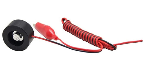
To create a touch plate, we purchased an inexpensive kit online, shown below.
Step One Strip ¼” of insulation from both wires and crimp a DuPont female pin connector on to each one as shown.
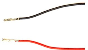
Step two Slide the female ends into a DuPont three-pin block leaving the middle connector slot empty as shown.
![]()
Step Three Slide the three-pin connector onto the GND Pin and SCL Pin as shown.
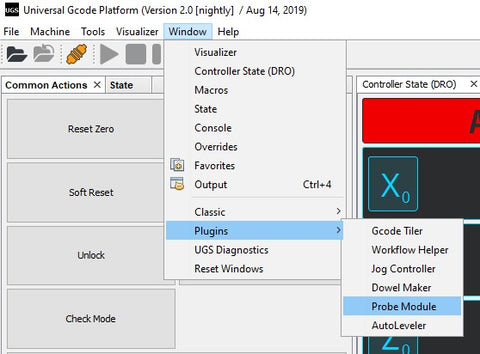
After the touch plate is connected to the controller, open UGS. Under the Window tab select Plugins and then Probe Module. Here you will enter the parameters of the touch plate. NOTE: the values must be in the same units as your jog controller to work correctly. The example below is in millimeters.
With the Probe Module open, choose the Units of measurement you prefer (inches or mm). Ignore the Endmill Diameter, it is only used for an X, Y touch plate. The Fast Find Rate refers to how quickly you want the bit to initially descend to the touch the plate; we chose 250mm/minute. The bit will retract the distance you choose in the Retract Amount and descend a second time to register the surface. Keep the Slow Measure Rate at 100mm per minute or less to ensure accuracy. (The values shown below will work well).
Click on the Z button and enter the thickness of the touch plate you are using. In this example, the thickness is 19.23mm. The Probe Distance is the maximum distance you want the probe to travel before it encounters the touch plate. As a best practice, keep that distance relatively short and manually jog your Z-axis down within that range of the surface of the touch plate. NOTE: the value must be negative to drive the bit down the Z-axis.
After these values have been entered, you are ready to Initiate the Probe. Make sure your machine has been homed, your workpiece is securely fastened in place and that it has been zeroed in the X and Y axes. Until you are comfortable using the probe, you may wish to use a piece of scrap material of a known thickness beneath the router bit. Place the touch plate flat on the surface of the workpiece. Attach the alligator clip to the router bit. Jog the bit down the Z-axis to within the Probe Distance you chose. CLICK the Initiate Probe button. The bit will descend until it touches the top of the touch plate. It will then retract and then slowly descend again to register the surface.
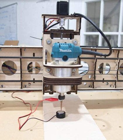
After the router bit retracts, remove the alligator clip from the bit and remove the touch place from the workpiece area. Then, in the Common Actions Screen click the Return to Zero Button and the bit will descend to the surface of the piece on which you set your touch plate.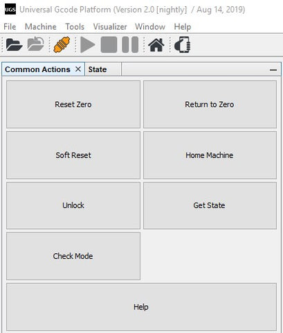
As a best practice, the probe should be disconnected from the controller after every use. This will minimize the risk that any loose wires moving as the machine operates can cause the GND and SCL pins to flex and break. However, if you wish to keep your touch plate connected, secure the wires to the controller mounting plate with a zip tie, and carefully bundle the excess wire along with the touch plate and the clip, then tuck them behind the mounting plate.
