Adding Bluetooth to your BobsCNC Router
In this article I’m going to show you how to add Bluetooth capability to any BobsCNC Router. There are at least three benefits to adding a Bluetooth module to your CNC. One, you no longer need to have a computer located right next to your CNC while it is running. Two, eliminating the USB removes a potential source of electromagnet interference (noise) that can play havoc with your controller. Three, by using a Bluetooth connection you can, with the right app, run your CNC from virtually any portable android device.
To get stared you’ll need some off-the-shelf components. You need a USB to TTL Serial Connector, a 4 Pin Wireless Bluetooth Serial RF transceiver Module, four AWG 26 Solderless Jumper Wires, and a 5V power supply for your controller.
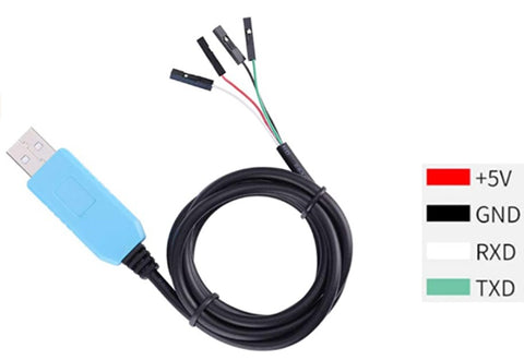
The PL230TA is a serial to TTL connector. It is only used to configure the HC-06 Module (shown below) for use with our controller. This allows the easiest method available to change the name, password, and baud rate of the HC-06 Module.
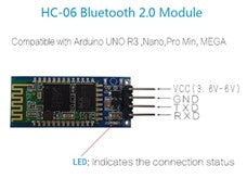
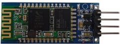
The HC-06 RS232 4 Pin Wireless Bluetooth Serial RF transceiver Module is used for short-range data wireless transmission and remote control. Once configured the module is used to connect to the CNCs controller
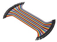
The Evolution Series CNC Routers require four female to female AWG 26 Solderless Ribbon Jumper Wires (available in bundles of various amounts depending on the supplier).
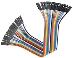
The KL Series CNC Routers require four male-to-female AWG 26 Solderless Ribbon Jumper Wires (available in bundles of various amounts depending on the supplier).
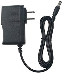
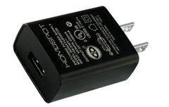
5VDC power supply or a USB Charger.
The baud rate for a HC-06 RS232 Wireless Bluetooth Serial RF transceiver Module is set at 9600. Since the controller on BobsCNC Router communicates at a baud rate of 115200 it is necessary to change the baud rate on the HC-06 RS232 Bluetooth Module. You can change the Module’s name, password, and baud rate by following the simple steps outlined below.
How to Change the Default Settings on the Bluetooth Module
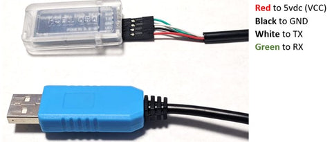
1. Connect the USP pin connectors to the Bluetooth Module. Be sure to follow the color coding below:
2. Use the USB plug to connect the PL230TA to your computer.
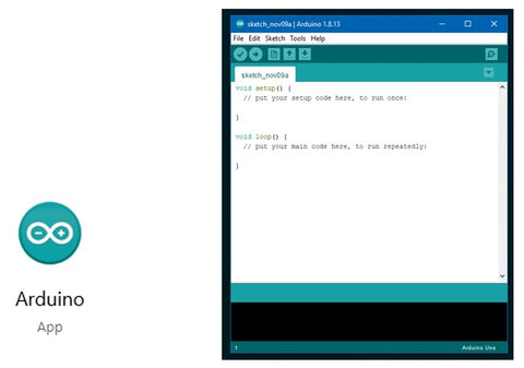
3. Click the Arduino icon and open the Arduino IDE
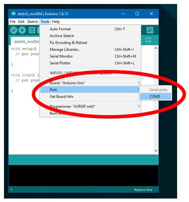
4. CLICK the Tool menu and select PORT. (Note the highlighted port in the illustration below the port is "COM5"). Your comport number may be different.
5. CLICK the Serial Monitor icon.
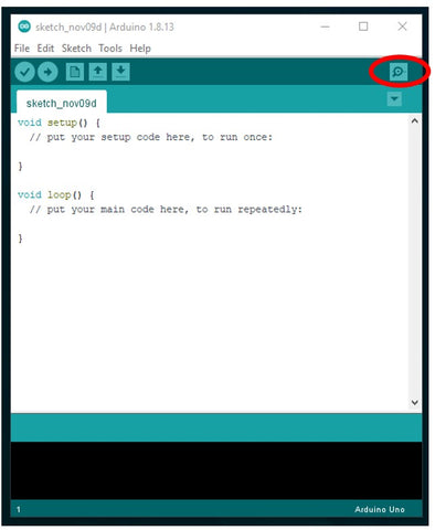
After the Serial Monitor opens, type "AT" in the command box and click ENTER.
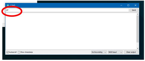
The edit commands you will use all begin with "AT."
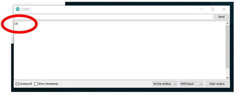
After clicking ENTER you will notice the response OK in the screen as shown below.
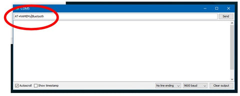
6. Change the name of your Bluetooth Module by typing the command "AT+NAME." In the illustration below note that the new name "My Bluetooth" was added immediately following the command.
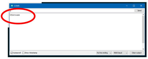
Once you have entered the name you're chosen click ENTER. The screen will display “OKsetname” indicating the Bluetooth Module has been renamed.
7. To Change the Module’s PIN number type, “AT+PIN” in the command box. “5555” is the default name of the module. Replace the "5555" with the PIN number of your choice and click ENTER.
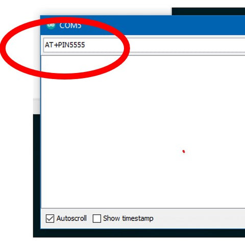
Again your command will be verified.

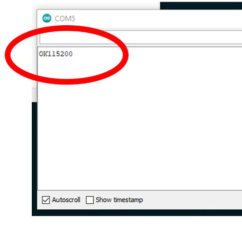
8. To change the baud rated type"AT+Baud8" in the command box. The Baud8 designation will change the baud rate to 115200.
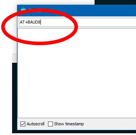
The change in baud will be verified after you click ENTER.
Congratulations, you have just changed the name, PIN number, and baud rate of the Bluetooth Module.
Disconnect the PLTA from the Bluetooth module..
If you are connecting a Bluetooth module to an Evolution series CNC Router connect the four female-to- female AWG 26 jumpers to the module as shown. Notice that a blue wire has replaced the white wire that was used with the of the PL230TA. Just make sure that you follow the wiring pattern that was shown at the start.
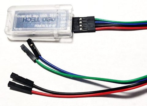
RED to vdc (VCC)
BLACK to GND
BLUE (TX) connects tp RX on the Controller
GREEN (RX) connects to the TX on the Controller.
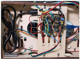
The photo below shows how a mounted controller is oriented to thee back of an Evolution Series CNC Router.
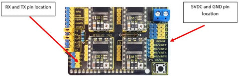
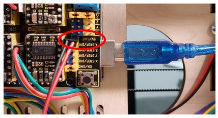
Next connect the Black wire to the GND on the controller and the RED wire to the 5vdc as shown.
Next connect the Blue wire to the RX PIN and the Green wire to the TX PIN.
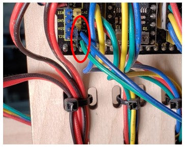
After making the connections, secure the Bluetooth module to the back of the gantry using a zip tie. You are now ready to pair the Bluetooth module to your computer.